Search


SITE PREPARATION AND INSTALLATION

Dikes: Dikes are often required to contain the volume of a certain portion of the tanks enclosed depending on the tank contents.
Dikes are used to protect surrounding property from tank spills or fires. In general, the net volume of the enclosed diked area should be the volume of the largest tank enclosed (single failure concept). The dike walls may be earth, steel, concrete, or solid masonry that are designed to be water tight with a full hydrostatic head behind it. Local codes and specifications may govern construction. If more than one tank is within the diked area, curbs or preferably drainage channels should be provided to subdivide the area in order to protect the adjacent tanks from possible spills.
Many codes, standards, and specifications regulate the location, design, and installation of storage tanks depending on their end use. Selecting the proper specification and providing adequate fire protection for the installation may allow lower insurance rates over the life of the installation. A partial list of applicable codes, standards, and specifications can be found at the end of this section.
Grounding : Metallic storage tanks used to store flammable liquids should be grounded to minimize the possibilities of an explosion or fire due to lightning or static electricity.

CATHODIC PROTECTION Cathodic protection can be applied to control corrosion that is electrochemical in nature where direct current is discharged from the surface area of a metal (the anodic area) through an electrolyte. Cathodic protection reduces corrosion of a metal surface by using a direct current from an external source to oppose the discharge of metal immersed in a conductingmediumor electrolyte such as soil, water, etc.

MATERIALS OF CONSTRUCTION

Vessel/Tank Materials
Metallic — Shop welded, field welded, and bolted storage tanks are customarily fabricated from mild quality carbon steel. Most common for welded tanks are A-36 structural steel and A-283 grade “C” structural quality carbon steel. Sheet gauge steels for bolted tanks are of commercial quality having a minimum tensile strength of 52,000 psi. A-612, A-515, and A-516 mild quality low carbon steels are used for fabricating the higher pressure storage products such as spheres and “bullets.”Various API and ASME Codes (listed in the References) to which the storage tank is fabricated, set forth the welding procedures, inspection procedures, testing requirements, and material selection. Some storage applications or service con-ditions (low temperature storage) require storage tanks to be fabricated from metals such as low alloy stainless steel, aluminum, or other specialty materials.

Non-Metallic — Older non-metallic tanks were customarily constructed from wood. Plastic materials have now replaced wood.  These materials have the advantage of being non-corroding, durable, low cost, and lightweight. Plastic materials used in the construction are polyvinyl chloride, polyethylene, polypropylene, and fiberglass-reinforced polyesters. The fiberglass- reinforced polyester (FRP) tanks are available in the larger sizes and are the most common. FRP tanks are suitable for outdoor as well as indoor applications. FRP tanks with special reinforced shells are designed for underground storage service. Above ground  tanks are primarily vertical, with or without top heads. Non-metallic tanks constructed of unreinforced plastics such as polyvinyl chloride or polyethylene materials are available in sizes up to about 6 ft in diameter by 11 ft high (2400 gallons). Horizontal underground FRP tanks will hold up to 12,000 gallons. Above ground vertical FRP tanks can store from 12,000 to 24,000 gallons, depending upon the shell construction. The temperature limits of plastic tanks are 40°F to 150°F. Color must be added to the outer liner for protection against ultraviolet radiation. The inner liner must be selected for compatibility with the chemical or product stored. Protection from mechanical abuse such as impact loads is a necessity. Good planning dictates that plastic storage should not be located next to flammable storage tanks. All closed plastic tanks should be equipped with pressure relief devices.
Protective Coatings:
 Internal—Use of internal coatings is primarily to protect the inside surface of the tank against corrosionwhile also protecting the stored contents from contamination. Consideration must always be given to such factors as the type of product being stored, type of coating available, type of surface to be coated, surface preparation, compatibility of coatings, and number of coats required to obtain maximum protection. Many types of internal coatings are available. Due to the unlimited types and applications, only a few will be described as follows:
Coal Tar — Among the oldest and most reliable coatings. Extremely low permeability; protects surface by the mechanical exclusion of moisture and air; extremely water resistant; good resistance to weak mineral acids, alkalis, salts, brine solutions, and other aggressive chemicals.
Epoxy Resin Coatings — Excellent adhesion, toughness, abrasion resistance, flexibility, durability, and good chemical and moisture resistance. Typical applications include linings for sour crude tanks, floating roof tanks, solvent storage tanks, drilling mud tanks, sour water, treated water, and pipelines.
Rubber Lining — Used as internal lining for storage tanks which are subjected to severe service such as elevated temperatures or for protection from extremely corrosive contents, such as concentrated chlorides and various acids such as chromic, sulfuric, hydrochloric, and phosphoric.
Galvanized — Galvanizing (zinc coating) is highly resistant to most types of corrosion. Bolted steel tanks are ideally suited for galvanizing since all component parts are galvanized by the hot-dip process after fabrication but before erection. Galvanized bolted tanks are recommended where the oil produced contains sulfur compounds and/or is associated with hydrogen sulfide gas. Galvanizing is also effective against corrosion in seacoast areas where atmospheric salt conditions accelerate
corrosion problems.
External — The basic requirements for external coatings are appearance and weather protection. Numerous types of external coatings are available, ranging from basic one-coat primers to primers with one or more topcoats. Environmental conditions usually dictate the extent of coating applied. Offshore and coastal installations require  more extensive coatings as compared to inland locations.

Energised, yet powerless

Trapped in an unaffordable energy paradigm, Pakistan’s economy has been experiencing crippling power shortages while its government is mired in mounting circular debt generated by this very paradigm. Last week, the demand and supply gap in power generation crossed 8000 MWs – the highest in the country’s history. Acute power outages have wrought havoc on households and industry. The mountain of circular debt keeps rising at the rate of one billion rupees per day! If, in order to eliminate circular debt, the government passes on the full cost of this unaffordable power to the people, there will be rioting on the streets. How did the country land in such a deadly trap?

Both problems are rooted in the flawed energy policies pursued for decades. Even when the rest of the world made drastic changes in their energy paradigms after the oil shocks of 1973 and 1979 and moved away from expensive oil to coal and hydro for power generation, Pakistan’s energy planners continued with suicidal policies as if oil was still selling at two dollars a barrel as in the 1960s, rather than over $100 a barrel.

Sitting on top of one of the largest coal reserves in the world, and still suffering power shortages, blackouts and breakdowns, Pakistan’s power sector has notoriously neglected cheap indigenous sources of energy and remained glued to the temptations of expensive, imported fuel. That has strangulated economic growth and made electricity an unaffordable luxury rather than a necessity of modern life.

Pakistan’s power mix is roughly divided in three equal parts – with oil, natural gas and hydro each contributing about 32 percent. The rest is taken by nuclear (two percent), coal (one percent) and renewables. The problems of power shortages and circular debt lie right there embedded in this irrational and unaffordable energy mix. Much of the world uses cheap coal-based power (30-50 percent cheaper than oil based) for 40 percent or more of its power mix, but Pakistan uses cheap coal power for only one percent of its power mix and that keeps power unaffordable for both the people and the government.

Most countries also make minimal use of expensive oil-fired power generation to keep power supply cheap and affordable. Worldwide, oil for power generation, is used for only six percent of total power production. Many countries use oil for less than five percent – and India uses oil for even less than one percent – of power production. But Pakistan has continued to use expensive oil-based power generation for one-third of its power mix.

A bigger disaster was planned under the so-called ‘new’ 25-year energy plan (2005-30) introduced during Shaukat Aziz’s time. This aimed to raise Pakistan’s dependence on imported oil for power generation to 50 percent by 2030, when even oil rich Gulf countries were reducing their share of oil in their power production!

World over, coal-based power is cheap and the largest source of power generation. The abundance of this cheap power in the power mix of a country pulls down the average price of power and makes electricity cheap and affordable. Pakistan today produces less than 20,000 MWs of power from all sources of energy – private and public. If Pakistan were to produce 100,000 MWs of power from its coal reserves (five times its current production) and kept producing the same for the next 100 years, it would have consumed only one-fourth of its coal reserves! Why then hasn’t the country made use of its abundant coal reserves to provide cheap power?

The one and only time a major coal-fired power project was actually started was in 1996 when four plants of 1300 MWs each were being installed over a six-year period at the low cost of 4.6 cents/KWh. That project fell victim to the usual politics of Pakistan. Since then, not a single MW of coal-based power has been added, while oil-fired power projects three to four times more expensive continued to be added to the power mix making electricity increasingly unaffordable. In fact, the energy planners of Pakistan in the early years of its independence were much better tuned to the realities of this country, for coal-based power contributed 60 percent of the country’s power production in 1948.

Coal-based power is no rocket science; there is no reason why it should take ages to bring several power plants on stream. It is intermediate technology, has been tried and tested for over 200 years and it takes an average of 36 months for a coal-fired power project to come on stream.

With only one percent of coal-based power in its power mix, Pakistan has a long way to go to rectify the damaging consequences of its faulty energy paradigm. But we have been using the wrong end of the stick to address the problem. The problem of power outages and circular debt cannot be solved by endless raises in power tariffs. It cannot be solved by massaging symptoms and not attacking the root cause – the irrational and unaffordable energy paradigm that continues to produce more problems than power for Pakistan.

Pakistan should offer attractive incentives for coal-based power projects, encourage shifting existing oil-based power plants to coal, and freeze new power generation from all sources except coal – until an affordable balance in power mix is achieved. Other countries have done it and so can Pakistan. Until Pakistan’s energy mix has more than 50 percent of coal-based power, the problems of expensive, unaffordable energy and circular debt will remain. But the urgency and seriousness required to tackle this national emergency are nowhere on display, nor have such projects come on stream.

Coal is available in every province with Sindh sitting on an estimated 175 billion tonnes of coal. Due to the 18th Amendment provinces also have greater autonomy in the matter. While every province has organisations dealing with coal-based power, they appear either to suffer from the problem of not knowing how to go about this task in world markets or too many cooks are spoiling the broth.

The News...........Oct 08,2011

LPG body wants its views heard

LAHORE: The Liquefied Petroleum Gas Association of Pakistan (LPGAP) has sought an appointment from the Standing Committee of the National Assembly on Petroleum and Natural Resources to clear its stance on the LPG Policy 2011.
The government will suffer an annual loss of Rs4 billion due to implementation of the LPG Policy 2011, the association said in its letter sent to the NA body.
The association also wants to suggest increasing the domestic production of LPG by 60 percent and demand curbs on its smuggling from Iran.
LPGAP said that the Oil and Gas Regulatory Authority Chairman and the Minister for Petroleum did not give them appointment to hear the viewpoint of the industry on the LPG Policy 2011.
The association said that it wants to present its findings on how to make LPG affordable, how to ensure its availability in remote areas at reasonable price, and how to maximize returns for the government on its investment in the LPG sector.
The letter further states that the association wants to explain the reasons why LPG distributors are not being brought into the regulatory ambit of OGRA, how a Public sector utility company is facing pressure to takeover a bankrupt company and what the result would be for the utility company?
LPGAP said that on September 27, Irfan Khokar gave a briefing to the members of the NA Committee on the alleged amassing of billions of rupees by the LPG marketing companies; a claim that remains unsubstantiated.
“Khokar does not hold a distribution agency of any LPG marketing Company, was dismissed from the Federal Investigation Agency on charges of malpractice, was also dismissed from a leading LPG marketing company on charges of fraud, his cheques, presented to the same company in lieu of money owed were dishonoured,” the letter said.
The association said that the Lahore High Court has suspended the main features of the LPG Policy 2011, including imposition of petroleum levy, compulsory import of LPG by the marketing companies and preferential treatment to public sector companies for allotment of LPG.
LPGAP pointed out that the progress made on the auto-gas through notifications made by OGRA notifications on safety standards conforming to NFPA-58, have been abandoned and now, once again, OGRA, at its discretion, will prescribe new standards which are unspecified.

The News International  ........Oct 08,2011.

CIO Pakistan: IT Industry, an answer to the energy crisis

The demand for natural gas and oil demand has increased manifold, likely to burden the economy further as a result of growing Middle East crisis. The government has planned major initiatives including three gas import pipelines, Gwadar port as energy hub and LNG import to meet energy shortage.
Pakistan’s economic growth is heavily reliant on its textile industry, contributing over $10 billion annually in terms of foreign exchange by consuming total cotton crop of the country. During last fiscal year, the textile industry exports have contributed $14 billion in country’s total exports of $25 billion. But it is also true that textile industry is losing 30% of the production due to prevailing energy shortage. Installation of Captive Power Plants (CPPs) by the spinning industry has also failed to deliver desired results, as availability of gas as a cheap fuel for these CPPs is becoming a question mark with every passing day. The textile industry was already denied Sui gas for over 100 days during the last fiscal. It is also for the first time in the history that the SNGPL has cut the supply to the textile industry during summer this year. Textile industry has yet to witness the worst in coming winter. The government is fully attentive to the fact and trying its level best to ensure uninterrupted electricity and gas to the industry. Especially, President Asif Ali Zardari has been very vigilant to the situation, which is highly appreciable act on his part.
An out of box solution has become an urgent need of the hour to deal with unprecedented energy shortage in the country, creating a deep dent in national economy since November 2007. Chances of meeting energy shortage in near future are dismal, at least for another seven years. This is therefore right time to re-evaluate the potential of various segments of economy in order to reshuffle the priorities in a highly emergent situation like this. The government policymakers should consider diversification of economic model and start thinking beyond traditional economic areas like textile industry. An extraordinary dependence on textile and agriculture since independence is losing country’s competitive edge fast, which is compounded by the prevailing energy crisis. Unfortunately, all the trade policies are entirely focused on textile industry, which is highly power-intensive and present energy shortage has resulted into massive unemployment.
Unlike India, Pakistan’s IT sector consists of a web of small firms and many of the entrepreneurs started from very low levels to make entry in the business.The industry revenues are exceeding $2 billion a year and are projected to reach $11 billion by 2016, according to Pakistan Software Houses Association (P@SHA). Many firms are seeing their sales grow at an annual rate of over 30%. This target can be achieved much earlier than 2016 provided the government is supportive the growth of IT industry. Pakistan has been able to achieve these growth rates despite ranking 120th on the infrastructure and logistics components of the World Bank’s Logistics Performance Index.
The Pakistan Software Export Board (PSEB) has recently been quoted in the press that Pakistan is producing around 25,000 IT professionals every year to meet growing requirement of domestic and international markets. Out of total number of such professionals, approximately 50 per cent enter the job market, according to the data. At present, an estimated 150,000 IT professionals are available in Pakistan against around 3 million IT engineers in India. However, the current pool of IT experts and engineers available in the country is not sufficient to meet the domestic requirements. To achieve targeted results, the government needs to take several steps to increase the number of IT experts and engineers with a focus on the growth of skilled human resource pool for the country’s IT industry. The best way to achieve growth in IT sector of Pakistan is to follow the Indian model.
A shift in government focus towards the IT industry may ease down pressure on the economic growth of the country. The IT industry is not as energy-intensive as the textile is. It is important to note that the IT industry in Pakistan is not as power-intensive as the textile is. The IT firms in Pakistan have not closed their operations even for a single day due to power shortfall as the computer machines are not as power intensive as the spinning looms are.

India’s software and services exports have been rising rapidly. The annual growth rate is around 45% in IT services and nearly 55% in IT-enabled services (ITES), such as call centres, Business Process outsourcing (BPO) and other administrative support operations. Together they are grown to 25% per annum. Despite the fact that Indian share in  the world market for information technology services is yet very negligible, this sector has been growing at a scorching pace, helped by a large pool of English speaking workers, nearly 3 million engineers and the increasing tribe of tech-savvy entrepreneurs in the country. The information Technology industry currently account for 7% of India’s GDP. Software service exports in India increased from US$0.50 million in 1990 to $5.9 billion in 2000-01 to 23.6 billion dollars in 2005-06 recording a 34% growth with a compound annual growth of over 25% per annum until 2010. The impact of software and IT enabled service exports of around $60 billion on the economy is likely to be profound. One manifestation is that India notched up a current account surplus in 2001-02 for the first time in 24 years.
Having a strong Pakistan IT industry is very much possible with concerted efforts on the part of the government, and host of other factors like private initiatives, emergence of software technology parks, clustering and public private partnerships. India formulated the national vision to promote software industry in India in the early 1980s and took its IT industry exports to $60 billion in 20 years. Pakistan IT industry has a potential higher than Indian IT industry and earn more foreign exchange in next 20 years provided the required focus of the government is there.

Gas shortage cripples $1 billion new Engro plant


KARACHI: Engro Corporation’s flagship fertiliser plant, built at a cost of over $1 billion, has remained shut for half of the time since its inauguration in January.
“When the agreement was signed with the government in 2006, we could not imagine that the supply of our basic raw material will be stopped,” said Khalid Mir, Vice President Marketing at Engro. “This is the first time in 50 years that government has turned back on its commitment with us.”
Engro has seen recurring disruptions in supply of gas to its new fertiliser plant, which has a capacity to produce 1.3 million tons of urea a year, an addition that has made Pakistan self-sufficient in soil fertiliser.
An energy crisis in the country has forced the authorities to reduce gas supply to fertiliser plants to divert it to power plants, textile factories and households.
Gas, chemically known as methane, is the basic ingredient to make ammonia, which is mixed with carbon dioxide to make urea. Without gas there is no way of making fertiliser.
Plant Production Manager Mudasir Rathore said that the plant has not been built to handle sudden closure of gas supply. “These plants are designed to run non-stop for three years at a stretch. Life of our equipment and machinery has been reduced by a year because of abrupt cuts.”
Engro’s new plant Enven, along with Pak-Arab Fertilizer, Dawood Hercules, Fauji Fertilizer Bin Qasim and Agritech, rely on Sui Northern Gas Pipelines Limited (SNGPL).
The gap in gas supply and demand has risen to over one billion cubic feet per day (BCFD) over the last five years as production remains stagnant at 4.2 BCFD.
Mir said that the sovereign agreement with the government ensures the plant 100 million cubic feet per day (MMCFD) of gas. “SNGPL is bound to follow the contract. Unfortunately that is not being done.”
The company has taken the case to court, but Mir insists that the government is holding all the cards and legal battle will not be of any benefit.
Pakistan’s annual demand for fertiliser stands at 6.9 million tons against total installed capacity of 6.3 million tons. But gas outages mean the local plants will produce 4.9 million tons this year and 1.5 million tons will have to be imported, he said.
“Everyone must realise that giving gas to fertiliser companies makes better economic sense than running power plants on it. Power plants have an alternative, which is furnace oil.”
The cash-strapped government depends on Pakistan State Oil (PSO) to import fuel for power producers. But the crippling inter-corporate circular debt has brought PSO on the verge of default on import payments more than once.
Engro has been increasing the price of fertiliser to make up for the production loss at its new plant, Mir said. “We can’t help it. We have to pay off billions of rupees of loans and that’s the only way to keep the revenue stream running.”
In the last two years, fertiliser price has increased to Rs1,700 per bag from just Rs800. The government subsidises gas which is used in making fertiliser.
“Even if the government removes all subsidies, the price of fertiliser will rise only by Rs380 per bag. The cost of imported fertiliser is Rs3,000 per bag. That is the point we want to make. Can farmers afford to pay this much money?” Mir said.
Engro officials said that the corporation’s other projects also face problems because of the government’s failure to meet its commitments. “International lenders who have invested in the project wonít take risk with other investments in the country.”

The News International ....Oct 08,2011.

STORAGE CLASSIFICATION

Above Ground
Atmospheric — Atmospheric pressure tanks are designed and equipped for storage of contents at atmospheric pressure. This category usually employs tanks of vertical cylindrical configuration that range in size from small shop welded to large field erected tanks. Bolted tanks, and occasionally rectangular welded tanks, are also used for atmospheric storage service.
Low Pressure (0 to 2.5 psig) — Low pressure tanks are normally used in applications for storage of intermediates and products that require an internal gas pressure from close to atmospheric up to a gas pressure of 2.5 psig. The shape is generally cylindrical with flat or dished bottoms and sloped or domed roofs. Low pressure storage tanks are usually of welded design. However, bolted tanks are often used for operating pressures near atmospheric. Many refrigerated storage tanks operate at approximately 0.5 psig.
Medium Pressure (2.5 to 15 psig) — Medium pressure tanks are normally used for the storage of higher volatility intermediates and products that cannot be stored in low pressure tanks. The shape may be cylindrical with flat or dished bottoms and sloped or domed roofs. Medium pressure tanks are usually of welded design. Welded spheres may also be used, particularly for pressures at or near 15 psig.
High Pressure (Above 15 psig) — High pressure tanks are generally used for storage of refined products or fractionated components at pressure above 15 psig. Tanks are of welded design and may be of cylindrical or spherical configuration.
Underground:
Gas processing industry liquids may be stored in underground, conventionally mined or solution mined caverns. No known standard procedures are available for this type storage; however, there are many publications and books covering the subject in detail.

WORKING PRESSURES
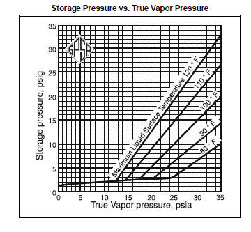
A design working pressure can be determined to prevent breathing, and thereby save standing storage losses. However, this should not be used in lieu of any environmental regulatory requirements regarding the design of storage tanks. The environmental regulatory requirements for the specific location should be consulted prior to the design of storage facilities. Generally there are regulatory requirements specifying the type of storage tank to be used, based on the storage tank capacity and the vapor pressure of the product being stored. In addition there are usually specific design requirements, for example in the type of seals to be used in a floating roof tank. The working pressure required to prevent breathing losses depends upon the vapor pressure of the product, the temperature variations of the liquid surface and the vapor space, and the setting of the vacuum vent.
Above fig is presented as a general guide to storage pressures for gasolines of various volatilities in uninsulated tanks , using the following assumptions:
· Minimum liquid surface temperature is 10°F less than the maximum liquid surface temperature.
· Maximum vapor space temperature is 40°F greater than the maximum liquid surface temperature.
· Minimum vapor space temperature is 15°F less than the maximum liquid surface temperature.
· Stable ambient conditions (ambient temp. 100°F).
These temperature variations are far greater than would be experienced from normal night to day changes. Therefore, the lower, nearly horizontal line, which shows a required storage pressure of 2.5 psig for the less volatile gasolines is conservative and allows a wide operating margin.
Maximum liquid surface temperatures vary from 85 to 115°F. Sufficient accuracy will generally result from the assumption that it is 10°F higher than the maximum temperature of the body of the liquid in a tank at that location. Example  — To illustrate the use of above Fig., suppose a 24 psia true vapor pressure (TVP) natural gasoline is to be stored where the liquid surface temperature may reach a maximum of 100°F. A vertical line extended upward from the 24 psia mark at the bottom of the chart intersects the 100°F line at 9.3 psig. The design pressure of the tank should be a minimum of 10.23 psig (9.3 psig + 10%).

Fig. given below can be used as follows:
· As quick reference to determine true vapor pressures of typical LPGs, natural gasolines, and motor fuel components at various temperatures.
· To estimate the operating pressure of a storage tank necessary to maintain the stored fluid in a liquid state at various temperatures.
· For converting from true vapor pressure to Reid Vapor Pressure (RVP).
· For simple evaluation of refrigerated storage versus ambient temperature storage for LPGs.

Example — Determine the TVP of a 12 psi RVP gasoline. In addition, estimate the design pressure of a tank needed to store this same 12 RVP gasoline at a maximum temperature of 120°F. Using Fig. 6-4, a vertical line is extended upwards from the 100°F mark (100°F is used as the reference point for determining RVP) at the bottom of the chart to the intersection of the 12 psi RVP line, read true vapor pressure of 13.2 psia. A vertical line is also extended from the 120°F mark to intersect the 12 RVP gasoline line. Now going horizontal, the true vapor pressure axis is crossed at approximately 18.1 psia. The storage tank should therefore be designed to operate at 18.1 psia (3.4 psig) or above. The design pressure of the tank should be a minimum of 10% above the operating gauge pressure
or approximately 18.5 psia.
TYPES OF STORAGE
Above Ground
For operating pressures above 15 psig, design and fabrication are governed by the ASME Code, Section VIII. 
Spheres — Spherical shaped storage tanks these are generally used for storing products at pressures above 5 psig.

Spheroids — A spheroidal tank is essentially spherical in shape except that it is somewhat flattened. Hemispheroidal tanks have cylindrical shells with curved roofs and bottoms. Noded spheroidal tanks are generally used in the larger sizes and have internal ties and supports to keep shell stresses low. These tanks are generally used for storing products above 5 psig.

Horizontal Cylindrical Tanks — The working pressure of these tanks (Fig. 6-7) can be from 15 psig to 1000 psig, or greater. These tanks often have hemispherical heads.

Fixed Roof — Fixed roofs are permanently attached to the tank shell.Welded tanks of 500 barrel capacity and larger may be provided with a frangible roof (designed for safety release of the welded deck to shell joint in the event excess internal pressure occurs), in which case the design pressure shall not exceed the equivalent pressure of the dead weight of the roof, including rafters, if external.

Floating Roof — Storage tanks may be furnished with floating roofs (Fig. 6-8) whereby the tank roof floats upon the stored contents. This type of tank is primarily used for storage near atmospheric pressure. Floating roofs are designed to move vertically within the tank shell in order to provide a constant minimum void between the surface of the stored product and the roof. Floating roofs are designed to provide a constant seal between the periphery of the floating roof and the tank shell.  They can be fabricated in a type that is exposed to the weather or a type that is under a fixed roof. Internal floating roof tanks with an external fixed roof are used in areas of heavy snowfalls since accumulations of snow or water on the floating roof affect the operating buoyancy. These can be installed in existing tanks as well as new tanks. Both floating roofs and internal floating roofs are utilized to reduce vapor losses and aid in conservation of stored fluids.


Bolted—Bolted tanks are designed and furnished as segmental elements which are assembled on location to provide complete vertical, cylindrical, above ground, closed and open top steel storage tanks. Standard API bolted tanks are available in nominal capacities of 100 to 10,000 barrels, designed for approximately atmospheric internal pressures. Bolted tanks offer the advantage of being easily transported to desired locations and erected by hand. To meet changing requirements for capacity of storage, bolted tanks can be easily dismantled and re-erected at new locations.

Flat-Sided Tanks— Although cylindrical shaped tanks may be structurally best for tank construction, rectangular tanks occasionally are preferred. When space is limited, such as offshore, requirements favor flat-sided tank construction because several cells of flat-sided tanks can be easily fabricated and arranged in less space than other types of tanks. Flat sided or rectangular tanks are normally used for atmospheric type storage.1
Lined Ponds2 — Ponds are used for disposal, evaporation, or storage of liquids. Environmental considerations may preclude the use of lined ponds for the storage of more volatile or toxic fluids. Linings are used to prevent storage liquid losses, seepage into the ground, and possible ground water contamination. Clay, wood, concrete, asphalt, and metal linings have been used for many years. More recently, a class of impervious lining materials has been developed that utilize flexible synthetic membranes. Commonly used lining materials are polyvinyl chloride, natural rubber, butyl rubber, and Hypalon®. Polyethylene, nylons, and neoprenes are used to a lesser extent. Some of the most important qualities of a suitable liner are:
· High tensile strength and flexibility.
· Good weather ability.
· Immunity to bacterial and fungus attack.
· Specific gravity greater than 1.0
· Resistance to ultraviolet-light attack.
· Absence of all imperfections and physical defects.
· Easily repaired.
Leak detection sometimes must be built into the pond system, especially where toxic wastes or pollutants are to be stored. Types of leak-detection systems that are commonly used are underbed (French) drainage system, ground resistively measurement, and monitor wells, and any combination thereof.

Pit Storage — Pit storage is similar to pond storage but is only used on an emergency basis. The use of this type of storage is limited by local, state, and federal regulations.
Underground:
Underground storage is most advantageous when large volumes are to be stored. Underground storage is especially advantageous for high vapor pressure products.
Types of underground storage are:
(1) caverns constructed in salt by solution mining or conventional mining. (2) caverns constructed in nonporous rock by conventional mining. (3) caverns developed by conversion of depleted coal, limestone, or salt mines to storage.


Refrigerated Storage
The decision to use refrigerated storage in lieu of pressurized storage is generally a function of the volume of the liquid to be stored, the fill rate, the physical and thermodynamic properties of the liquid to be stored, and the capital investment and operating expenses of each type of system.
The parameters involved in selecting the optimum refrigerated storage facility are:
· Quantity and quality of product to be stored.
· Fill rate, temperature, and pressure of incoming stream.
· Shipping conditions for the product.
· Composition of the product.
· Cooling media (air, water, etc.) available.
· Availability and cost of utilities.
The proper choice of storage and the proper integration of the storage facility with the refrigeration facilities are important to overall economy in the initial investment and operating costs. Fig given as under provides some general guidelines to use when selecting a storage system for propane.

When using refrigerated storage, the liquid to be stored is normally chilled to its bubble point temperature at atmospheric pressure. Refrigerated storage tanks normally operate at an internal pressure between 0.5 and 2.0 psig. In some cases, pressurized-refrigerated storage is attractive. In this type of refrigerated storage, the product to be stored is chilled to a temperature that allows it to be stored at a pressure somewhere between atmospheric pressure and its vapor pressure at ambient temperature. Refrigeration requirements normally include the following basic functions:
            · Cooling the fill stream to storage temperature.
            · Reliquefying product vaporized by heat leak into the system.
            · Liquefying vapors displaced by the incoming liquid.
Other factors which should be considered are:
            · Pump energy requirements
            · Barometric pressure variations
            · Product compositions
            · Non-condensables
            · Solar radiation effects
            · Superheated products


Important Properties of Natural gas

Properties of natural gas include gas-specific gravity, pseudocritical pressure and temperature, viscosity, compressibility factor, gas density, and gas compressibility. Knowledge of these property values is essential for designing and analyzing natural gas production and processing systems.
Because natural gas is a complex mixture of light hydrocarbons with a minor amount of inorganic compounds, it is always desirable to find the composition of the gas through measurements. Once the gas  omposition is known, gas properties can usually be estimated using established correlations with confidence.

Filters

Filter Separators :
General — This type of separator has a higher separation efficiency than the centrifugal separator, but it uses filter elements, which must periodically be replaced. An example filter separator is shown in Fig. Gas enters the inlet nozzle and passes through the filter section where solid particles are filtered from the gas stream and liquid particles are coalesced into larger droplets. These droplets pass through the tube and are entrained into the second section of the separator, where a final mist extraction element removes these coalesced droplets from the gas stream.

Design — The most common and efficient agglomerator is composed of a tubular fiber glass filter pack which is capable of holding the liquid particles through submicron sizes. Gas flows into the top of the filter pack, passes through the elements and then travels out through the tubes. Small, dry solid particles are retained in the filter elements and the liquid coalesces to form larger particles. Liquid agglomerated in the filter pack is then removed by a mist extractor located near the gas outlet. The approximate filter surface area for gas filters can be estimated from Fig. given below. The figure is based on applications such as molecular sieve dehydrator outlet gas filters. For dirty gas service the estimated area should be increased by a factor of two or three. The efficiency of a filter separator largely depends on the proper design of the filter pack, i.e., a minimum pressure drop while retaining an acceptable extraction efficiency. A pressure drop of approximately 1-2 psi is normal in a clean filter separator. If excessive solid particles are present, it may be necessary to clean or replace the filters at regular intervals when a pressure drop in excess of 10 psi is observed. However, as a rule, 25 psi is recommended as a maximum as the cartridge units might otherwise collapse. Removal of the filter pack is easily achieved by using a quick-opening closure. Various guarantees are available from filter separator manufacturers such as one for 100 percent removal of liquid droplets 8 microns and larger and 99.5 percent removal of particles in the 0.5-8 micron range. However, guarantees for the performance of separators and filters are very difficult to verify in the field. While most dry solid particles about ten microns and larger are removable, the removal efficiency is about 99 percent for particles below approximately ten microns. For heavy liquid loads, or where free liquids are contained in the inlet stream, a horizontal filter separator with a liquid sump, which collects and dumps the inlet free-liquids separately from coalesced liquids, is often preferred.


Separators

Process of Separation:
Momentum.  Fluid phases with different densities will have different momentum. If a two phase stream changes direction sharply, greater momentum will not allow the particles of the heavier phase to turn as rapidly as the lighter fluid, so separation occurs. Momentum is usually employed for bulk separation of the two phases in a stream.
Gravity Settling.  Liquid droplets will settle out of a gas phase if the gravitational force acting on the droplet is greater than the drag force of the gas flowing around the droplet. These  forces can be described mathematically using the terminal or free settling velocity.
Very small droplets such as fog or mist cannot be separated practically by gravity. These droplets can be coalesced to form larger droplets that will settle by gravity.
Coalescing. Coalescing devices in separators force gas to follow a tortuous path. The momentum of the droplets causes them to collide with other droplets or the coalescing device, forming larger droplets. These larger droplets can then settle out of the gas phase by gravity. Wire mesh screens, vane elements, and filter cartridges are typical examples of coalescing devices.

Filter Separators: A filter separator usually has two compartments.The first compartment contains filter-coalescing elements. As the gas flows through the elements, the liquid particles coalesce into larger droplets and when the droplets reach sufficient size, the gas flow causes them to flow out of the filter elements into the center core. The particles are then carried into the second compartment of the vessel (containing a vane-type or knitted wire mesh mist extractor) where the larger droplets are removed. A lower barrel or boot may be used for surge or storage of the removed liquid.
Flash Tank: A vessel used to separate the gas evolved from liquid flashed from a higher pressure to a lower pressure.
Line Drip: Typically used in pipelines with very high gas to liquid ratios to remove only free liquid from a gas stream, and not necessarily all the liquid. Line drips provide a place for free liquids to separate and accumulate.
Liquid-Liquid Separators: Two immiscible liquid phases can be separated using the same principles as for gas and liquid separators. Liquid-liquid separators are fundamentally the same as gas-liquid separators except that they must be designed for much lower velocities. Because the difference in density between two liquids is less than between gas and liquid, separation is more difficult.
Scrubber or Knockout: A vessel designed to handle streams with high gas-to-liquid ratios. The liquid is generally entrained as mist in the gas or is free-flowing along the pipe wall. These vessels usually have a small liquid collection section. The terms are often used interchangeably.

Separator: A vessel used to separate a mixed-phase stream into gas and liquid phases that are "relatively" free of each other. Other terms used are scrubbers, knockouts, line-drips, and decanters.
Slug Catcher: A particular separator design able to absorb sustained in-flow of large liquid volumes at irregular intervals. Usually found on gas gathering systems or other two phase pipeline systems. A slug catcher may be a single large vessel or a manifolded system of pipes.

Three Phase Separator: A vessel used to separate gas and two immiscible liquids of different densities (e.g. gas, water, and oil).
Parts of a Separator: Regardless of shape, separation vessels usually contain four major sections, plus the necessary controls. These sections are shown for horizontal and vertical vessels in Fig. The primary separation section, A, is used to separate the main portion of free liquid in the inlet stream. It contains the inlet nozzle which may be tangential, or a diverter baffle to take
advantage of the inertial effects of centrifugal force or an abrupt change of direction to separate the major portion of the liquid from the gas stream.The secondary or gravity section, B, is designed to utilizethe force of gravity to enhance separation of entrained droplets.It consists of a portion of the vessel through which the gasmoves at a relatively low velocity with little turbulence. In some designs, straightening vanes are used to reduce turbulence. The vanes also act as droplet collectors, and reduce the distance a droplet must fall to be removed from the gas stream. The coalescing section, C, utilizes a coalescer or mist extractor which can consist of a series of vanes, a knitted wire mesh pad, or cyclonic passages. This section removes the very small droplets of liquid from the gas by impingement on a surface where they coalesce. A typical liquid carryover from the mist
extractor is less than 0.1 gallon per MMscf. The sump or liquid collection section, D, acts as receiver for all liquid removed from the gas in the primary, secondary, and coalescing sections. Depending on requirements, the liquid section should have a certain amount of surge volume, for degassing or slug catching, over a minimum liquid level necessary for controls to function properly. Degassing may require a horizontal separator with a shallow liquid level while emulsion separation may also require higher temperature, higher liquid level, and/or the addition of a surfactant.
Separator Configurations :
Factors to be considered for separator configuration selection include:
· How well will extraneous material (e.g. sand, mud, corrosion products) be handled?
· How much plot space will be required?
· Will the separator be too tall for transport if skidded?
· Is there enough interface surface for three-phase separation (e.g. gas/hydrocarbon/glycol liquid)?
· Can heating coils or sand jets be incorporated if required?
· How much surface area is available for degassing of separated liquid?
· Must surges in liquid flow be handled without large changes in level?
· Is large liquid retention volume necessary?

Vertical Separators :
Vertical separators, are usually selected when the gas-liquid ratio is high or total gas volumes are low. In the vertical separator, the fluids enter the vessel striking a diverting baffle which initiates primary separation. Liquid removed by the inlet baffle falls to the bottom of the vessel. The gas moves upward, usually passing through a mist extractor to remove suspended mist, and then the "dry" gas flows out. Liquid removed by the mist extractor is coalesced into larger droplets which then fall through the gas to the liquid reservoir in the bottom. The ability to handle liquid slugs is typically obtained by increasing height. Level control is not critical and liquid level can fluctuate several inches without affecting operating efficiency. Mist extractors can significantly reduce the required diameter of vertical separators. As an example of a vertical separator, consider a compressor suction scrubber. In this service the vertical separator: · Does not need significant liquid retention volume.
                                                               

Horizontal Separators :
Horizontal separators are most efficient where large volumes of total fluids and large amounts of dissolved gas are present with the liquid. The greater liquid surface area in this configuration provides optimum conditions for releasing entrapped gas. In the horizontal separator,the liquid which has been separated from the gas moves along the bottom of the vessel to the liquid outlet. The gas and liquid occupy their proportionate shares of shell cross-section. Increased slug capacity is obtained through shortened retention time and increased liquid level.Fig also illustrates the separation of two liquid phases (glycol and hydrocarbon). The denser glycol settles to the bottom and is withdrawn through the "boot." The glycol level is controlled by a conventional level control instrument. In a double barrel separator, the liquids fall through connecting flow pipes into the external liquid reservoir below. Slightly smaller vessels may be possible with the double barrel horizontal separator where surge capacity establishes the size of the lower liquid collection chamber.
As an example of a horizontal separator consider a rich amine flash tank. In this service:
· There is relatively large liquid surge volume leading to longer retention time (this allows more complete release of the dissolved gas and, if necessary, surge volume for the circulating system).
· There is more surface area per liquid volume to aid in more complete degassing.
· The horizontal configuration would handle a foaming liquid better than a vertical.
· The liquid level responds slowly to changes in liquid inventory.
                

Spherical Separators : These separators are occasionally used for high pressure service where compact size is desired and liquid volumes are small.  Factors considered for a spherical separator are:
· compactness;
· limited liquid surge capacity;
· minimum steel for a given pressure.